A group of participants near the experimental facility with the POLI diffractometer at the FRM II reactor. From left to right: Earl Babcock, Zahir Salhi, Daniyar Berikov, Aleksey Gagarsky, Vadim Novitsky, Yuri Kopatch. 
Nuclei, the equilibrium shape of which in the ground state differs from the spherically symmetrical one, are called deformed. A deformed nucleus with a non-zero spin rotates and if it is polarized, then a z-axis of rotation occurs. The core deformation axis (symmetry axis) rotates around the z axis and the plane of rotation can make a certain angle with the z axis.
At the saddle point, the deformed core is described using the wave function of the DJМК top. Good quantum numbers are J, M and K, where J is the total momentum of the deformed nucleus, M is its projection onto a fixed z-axis in space and K is the projection of J onto the division axis (Fig. 1). It is usually assumed that not only J but also the K component is conserved from the saddle to the rupture.
Figure 1. Classical decomposition of the total angular momentum J into components K along the deformation axis (fission axis) and R, perpendicular to this axis. The projection of J onto a fixed z-axis in space is M 
During the fission of such a rotating nucleus, the fission fragments acquire a tangential velocity component at the initial moment of rupture of the neck, directed perpendicular to the deformation axis of the fissile nucleus. Thus, the trajectory of the fragment, instead of rectilinear, due to the Coulomb repulsion of fragments, becomes hyperbolic. Consequently, the axis of emission of fission fragments to infinity will not coincide with the deformation axis of the fissile nucleus at the moment of neck rupture, but will deviate from it by a certain small angle δ. Measuring this angle gives an idea of the rotation velocity of the core.
In the experiment, the direction of departure of the fission fragment from the target is registered. However, the orientation of the deformation axis at the moment of neck rupture remains unknown. To define it, a certain matchmark is required that characterizes this orientation. The angular distributions of particles accompanying the fission can serve as such a matchmark, since they are developed relative to the axis of deformation of the nucleus at the moment of rupture. It is important that their angular distributions are anisotropic relative to the deformation axis.
The effect of nuclear rotation, the so-called ROT effect, was first discovered in the angular distributions of α-particles from the ternary fission of the 235U nucleus using cold polarized neutrons [1]. However, the trajectories of motion of α-particles of ternary fission, developed at the moment of nuclear rupture, partially rotate along with the fission axis, since their motion is significantly influenced by the Coulomb field of flying fragments (Fig. 2). Therefore, to determine the rotation angle of the fission axis (the value of the ROT effect) in ternary fission, detailed trajectory calculations are required [2].
Figure 2. Schematic of the developed shift in the angular distribution of ternary fission α particles. PLF, PHF – initial directions of light and heavy fragments, respectively; Pα is the motion of the α particle at the moment of rupture. "+" and "-" denote the final directions of the object for opposite directions of neutron polarization 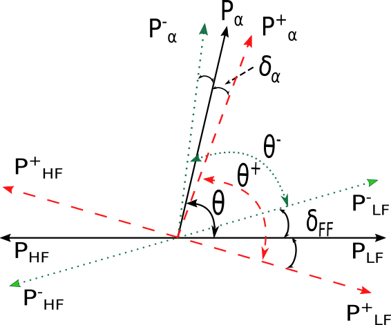
The so-called “instant” γ-quanta emitted using excited fission fragments can serve as a matchmark of the orientation of the deformation axis before the collapse of the nucleus. The search and detailed investigation of the ROT effect for prompt γ-quanta during the binary fission of 233U and 235U nuclei was first carried out by the authors [3-5]. An explanation of how γ-quanta emitted not at the moment of neck rupture, but using excited fission fragments can exhibit the ROT effect, was proposed by V. V. Novitsky [3], using the hypothesis of V. M. Strutinsky [6] on the alignment of fission fragment spins in a plane orthogonal to the fission axis. According to this model, at the moment of neck rupture of the fissioning nucleus, the spins of the excited fission fragments are aligned in a plane orthogonal to the axis uniting the centres of mass of the two fragments (hereinafter referred to as the “strain axis”) and their orientation does not change when the trajectory of the fragments deviates from the original direction of the strain axis (Fig. 3). The orientation of the fragment spins described above explains, in particular, the anisotropy of the emission of γ-quanta in fission relative to the axis of fragment expansion.
Figure 3. Schematic of the developed shift in the angular distribution of prompt γ-quanta from fission fragments. Pγ is the movement of the γ-quantum at the moment of rupture. "+" and "-" denote the final directions of the object for opposite directions of neutron polarization 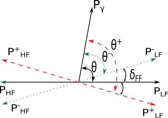
In the experiment, when the fragment detectors and the γ-quanta detectors are positioned in a plane orthogonal to the direction of the beam of longitudinally polarized neutrons, it manifests itself as an asymmetry in the count of coincidences of signals from the γ-quantum detectors and fragment detectors relative to the direction of polarization of the neutron beam. The asymmetry of the coincidence count is determined by the ratio:
![]() (1)
(1)
N+(θ) and N−(θ) consist the number of coincidences of signals from γ-quanta detectors and fragment detectors, positioned at an angle θ to each other in the plane orthogonal to the axis of the longitudinally polarized neutron beam, measured at two opposite directions of polarization of the neutron beam (Fig. 4).
Figure 4. Diagram of the detector part of the experimental facility. 1 - fission chamber, 2 - Al input chamber window, 3, 4 - fission fragment detectors based on position-sensitive low-pressure multiwire proportional counters (start and stop detectors), 5 - holder, 6 - scintillation plastic detectors of γ-quanta and neutrons. The fissile target is in the centre, between the starting detectors 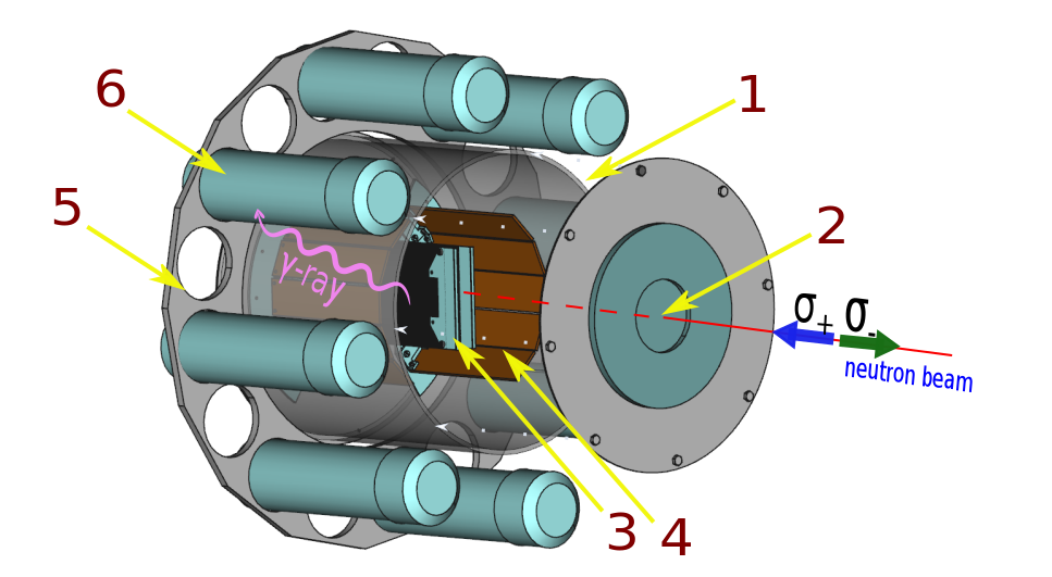
It is evident that
 (2)
(2)
F(θ) is a function describing the angular distribution of γ-quanta and F'(θ) is its derivative at the average position of the γ-quanta detector positioned at an angle θ, δ is the displacement angle of the fission axis. Thus, by measuring the asymmetry and determining the angular distribution function of γ-quanta, it is possible to determine the angle by which the trajectory of the fragment is shifted and consequently, the angular velocity and the direction of rotation of the fissile nucleus. It is important to note that for γ-quanta, unlike α-particles, determining the rotation angle does not require trajectory calculations and in this sense, is model-independent.
According to the model proposed in [3, 7], the rotation angle of the fissile nucleus, in turn, depends on the quantum numbers J and K (value of the angular momentum and its projection onto the deformation axis of the fissile nucleus, respectively) that characterize the fission channels. When a target nucleus with spin I captures a s-wave neutron (with orbital momentum equal to 0), a compound nucleus is developed in a state with spin ![]() and in a state with spin
and in a state with spin ![]() . In this case, the corresponding polarization of the compound core is equal to:
. In this case, the corresponding polarization of the compound core is equal to:
 (3)
(3)
pn is the degree of polarization of the neutron beam. Nuclei with transition state spins J± = (I ± 1/2) have different velocities and directions of rotation [8], that is, the sign of the rotation angle δ of the fission axis will be opposite for different states (see 4).
 (4)
(4)
ω is the angular velocity of rotation, K is the projection of angular momentum onto the fission axis, ℑ is the moment of inertia ratio of the fissile nucleus.
In the area of low neutron energies, the fission channels mix, that is, both resonances contribute to the fission cross section, but with an indefinite ratio of contributions to the fission cross section of both spin states of the compound nucleus. For a mixture of states and , the average asymmetry value is measured:
![]() (5)
(5)
It therefore follows, measurements of effects at resonances are required. An analysis of their physical nature will be more reliable that will allow to obtain data on the weights of the J and K channels. For such investigations, the 235U isotope was chosen that has a 3- resonance with an energy of 0.3 eV and a 4+ resonance with an energy of 1.14 eV (Fig. 5).
Figure 5. Spin-separated fission cross sections for 236U*. Red line corresponds to spin J = 3, green line corresponds to spin J = 4, black line corresponds to total cross section 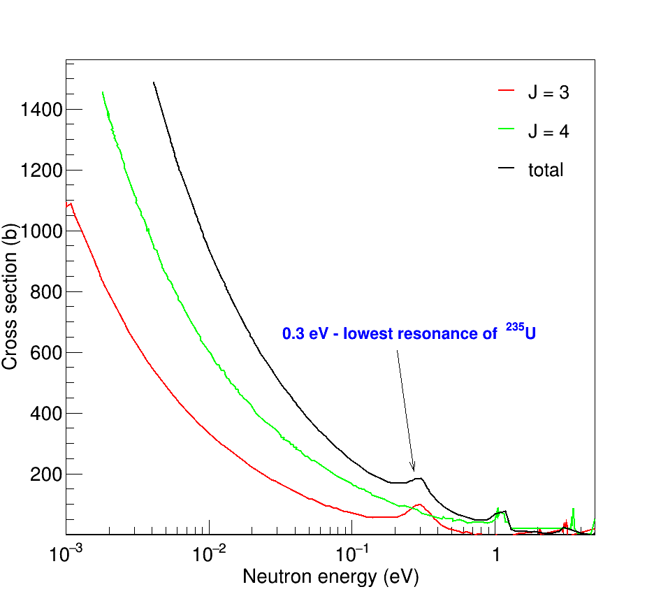
In 2018, for the first time, it was possible to measure the ROT effect for gamma rays in 235U fission at a low-lying resonance of 0.3 eV. The results obtained are consistent with the theory, however, for further research of the quantum mechanical properties of the fission process, it is advisable to carry out further work aimed at obtaining data for higher-lying resonances, as well as for other nuclei. In particular, the nuclei 241Am and 245Cm were proposed as candidates [9].
Such experiments can be started using a polarized neutron beam of the IBR-2 reactor. Despite the long duration of the reactor pulses, the resolution of the time-of-flight technique allows to resolve low-lying resonances up to several electron volts at flight path lengths of about 15-30 m. Further work on external neutron sources, such as nTOF (CERN) CSNS (China) or ESS (Sweden) can be implemented.
References
- F. Goennenwein, M. Mutterer, A. Gagarski, I. Guseva, G. Petrov, V. Sokolov, T. Zavarukhina, Yu. Gusev, J.von Kalben, V. Nesvizhevski, T. Soldner, Phys. Lett. B 652, 13 (2007);
- I.S. Guseva, Yu.I. Gusev, Bull. Russ. Acad. Sci. Phys. 71, 367 (2007);
- G.V. Danilyan, J. Klenke, V.A. Krakhotin, V.L. Kuznetsov, V.V.Novitsky, V.S.Pavlov, P.B.Shatalov, Phys. At. Nucl.72, 1812 (2009);
- G.V. Danilyan, J. Klenke, V.A. Krakhotin, Yu.N. Kopach, V.V.Novitsky, V.S.Pavlov, P.B.Shatalov, Phys. At. Nucl.74, 671 (2011);
- G.V. Danilyan, J. Klenke, Yu. Kopatch, V.A. Krakhotin, V.V. Novitsky, V.S. Pavlov, P.B. Shatalov, Phys. At. Nucl. 77, 677 (2014);
- Струтинский В. М. Об угловой анизотропии γ-квантов, сопровождающих деление // ЖЭТФ. – 1959. – Т. 37. – С. 861-863;
- G.V. Valsky, A.M. Gagarski, I.S. Guseva, D.O. Krinitsin, G.A. Petrov, Yu.S. Pleva, V.E. Sokolov, V.I. Petrova, T.A. Zavarukhina, and T.E. Kuzmina, Bull. Russ. Acad. Sci. Phys. 74, 767 (2010);
- A.M. Gagarski, I.S. Guseva, F. Goennenwein, Yu.N. Kopach, M. Mutterer, T.E. Kuz’mina, G.A. Petrov, G. Tyurin, V. Nesvizhevsky, Cryst. Reports 56, 1238 (2011);
- I. Guseva, Yu. Gusev, Nucl.Phys.A 1030 (2023) 122592.