Applied Research and Engineering Sciences
- Investigation of internal stresses in structural materials and manufactured goods using neutron diffraction
- Investigation of features of internal structure of cultural and natural heritage objects, structural materials and industrial products
- Investigation of crystallographic texture in structural materials, biological objects and rocks
- Investigation of radiation damage effects in solid state materials
G. D. Bokuchava, I. V. Papushkin, A. A. Kruglov
For the investigation of internal stresses in materials, for many years various non-destructive testing techniques have been used: x-ray diffraction, ultrasonic scanning, various magnetic techniques (measurements of magnetic induction, permeability, anisotropy, the Barkhausen effect, magnetoacoustic effects). However, all of these techniques have certain limitations. Such as, X-ray scattering and magnetic techniques can be used to study stresses only close to the material surface due to their small penetration depth; in addition, the use of magnetic techniques is limited to ferromagnetic materials. Also, magnetic and ultrasonic techniques are strongly influenced by the occurrence of texture in the sample. Among all these techniques, the investigation of stresses using neutron diffraction stands in a special place since unlike traditional techniques, neutrons can penetrate the material to a depth of up to 3 cm for steel and up to 10 cm for aluminum.
The uniqueness of the neutron technique for studying internal stresses is due to the following crucial features:
- preservation of the integrity of the object under study (non-destructive testing);
- large depth of scanning of the investigated material (up to 3 cm for steel);
- high spatial resolution (up to 1 mm in any direction) with the allocation of a small scattering volume (gauge volume) inside the test sample;
- the use of the TOF technique allows to observe several Bragg reflections simultaneously and thus to determine strains for different directions [hkl] in a crystal in order to study the anisotropy of material stresses;
- for a multiphase material, neutrons provide information on the stress distribution for each phase separately;
- strain values are usually of the order of Dd/d ~ 10-3 ¸ 10-4 therefore, high resolution of the diffractometer is required for measurements;
- typical accuracy for residual stresses is 20 ¸ 40 MPa;
- analysis of the shape and width of diffraction peaks allows to estimate microstrains, crystallite size, dislocation density and point defects in the material;
- systematic deviations of the Bragg peak intensities of the material under study from the peak intensities of an isotropic powder sample provide information about the texture in the sample for each phase separately.
To carry out neutron diffraction investigations of internal mechanical stresses in new promising materials and bulk manufactured goods at the IBR-2 pulsed reactor, a specialized Fourier stress diffractometer FSD [1] (Fig. 1) has been developed and successfully operates at FLNP JINR. A special correlation technique - the use of a fast Fourier chopper for modulating the intensity of the primary neutron beam and the RTOF technique for data accumulation allows to obtain diffraction spectra with the required high resolution Δd/d ≈ 2÷4×10⁻³. During the operation of the FSD, the real capabilities of the diffractometer in meeting certain issues were determined and the basic research areas were developed concerning the achieved levels of resolution and luminosity, as well as the available range of interplanar distances dhkl.
The main part of the tasks is related to the determination of residual stresses in finished components and structures after various technological operations (welding, rolling, moulding, hardening, others). The results of such operations help to optimise the residual stress state in various cross-sections of the component and accordingly, improve the operational properties and lifetime of the component. Often, neutron measurement data are also used for comparison with the results of calculations using the end element technique and the subsequent development of theoretical models for an adequate description of technological processes and a correct estimation of the stress level in the entire component.
Fig.1. Schematic of the FSD Fourier diffractometer at the IBR-2 reactor 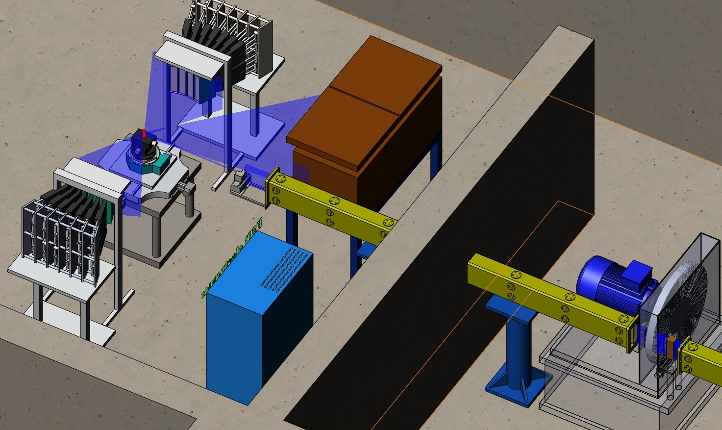
For instance, in [2], a detailed investigation of residual stresses in a plate made of structural steel S355J2+N, manufactured by laser welding, has been carried out. It has been discovered that the distribution of residual stresses along the X scan coordinate across the weld is sign-alternating (Fig. 2), with the distribution maxima (~400–460 MPa) symmetrically relative to the weld centre in the heat-affected zones (HAZ). The level of residual stresses decreases rather sharply at a distance from the HAZ. The maximum value is the stress tensor component σX, directed along the weld line with a tensile character in the HAZ.
In addition to neutron diffraction data, numerical calculations have been carried out using the finite element method (FEM). The developed model of the laser welding process allows to calculate the distribution of residual stresses depending on the parameters of the welding process for the most common structural materials. A comparison of the neutron data and the results of calculations using the finite element method have shown their good agreement that indicates the reliability of the developed theoretical model of the laser welding process. This information can serve as a basis for the development of specific technological recommendations to obtain the desired level and profile of residual stresses.
Fig.2a. Map of the distribution of the σX component of residual stresses based on the results of calculations using the FEM 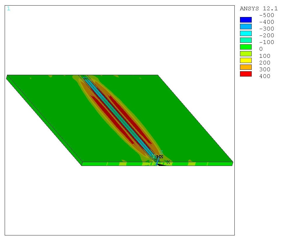
Fig.2b. Distribution of residual stress tensor components measured using neutron diffraction across the weld (symbols) 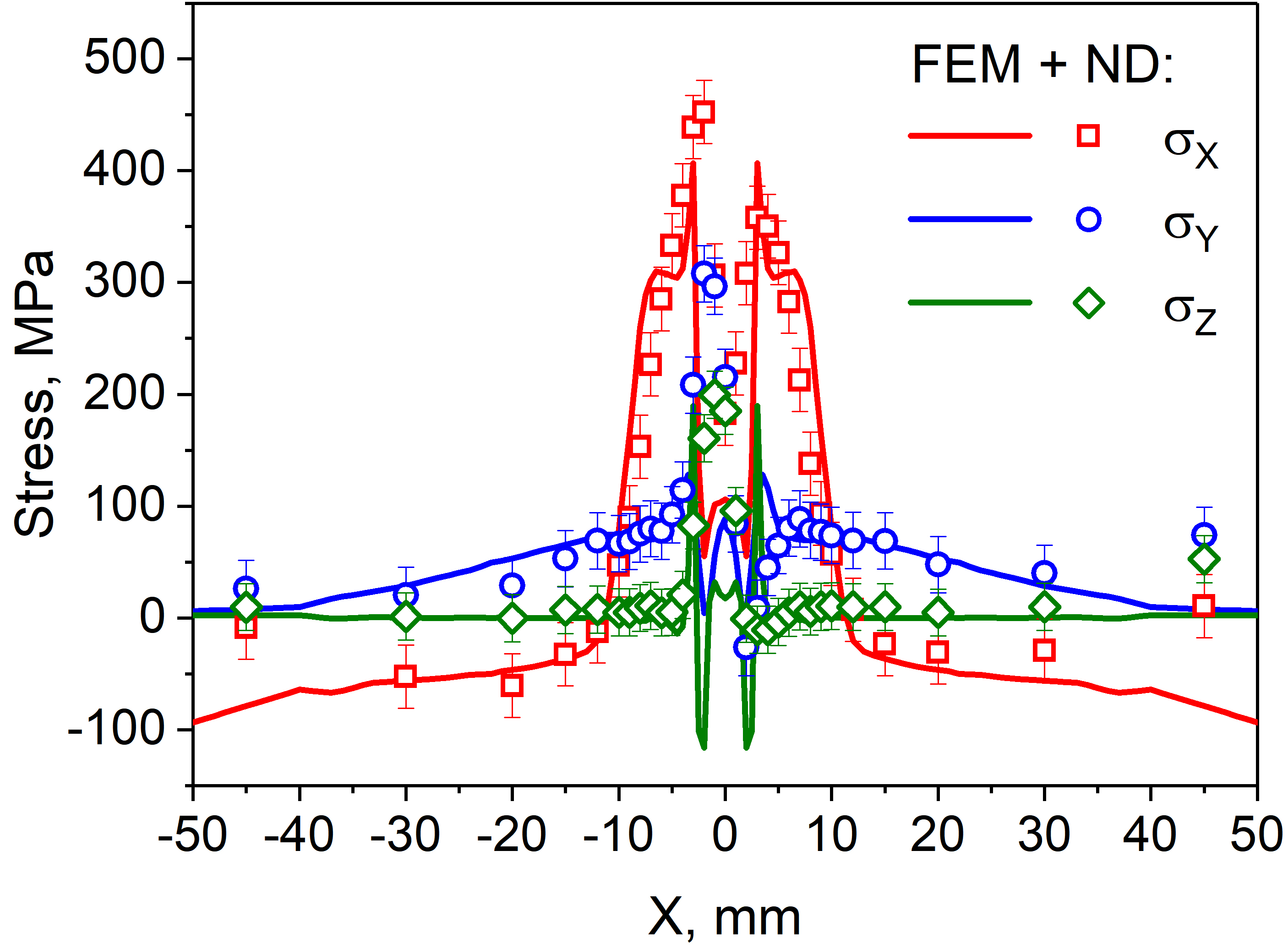
Fig.2c. Dislocation density distribution during scanning across the weld 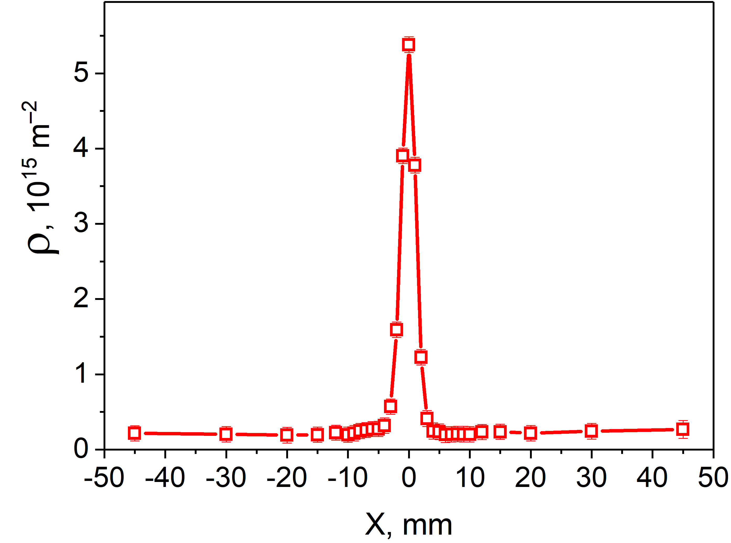
In addition, high resolution neutron diffraction data have allowed to estimate the degree of peak broadening as compared to the resolution function of the instrument and to obtain information on the distribution of residual microstrains and consequently, the dislocation density in the material under study. In this sample, the maximum level of microstrain in the material reaches 4.8×10⁻³ and the position of the maximum in its distribution coincides with the position of the centre of the weld. From these data, the dislocation densities in the material have also been estimated and reach rather high values of ~5.4×10¹⁵ m–2, typical for highly deformed weld materials.
Another application of neutron diffraction is the in situ investigation of the behavior of new promising materials (composites, gradient materials, various steels and alloys, others) under various external impacts (load, temperature). Usually, in such tasks, the interaction of several phases in one material and their combined effect on the elastic properties and residual stresses are studied. These investigations are significant for the development of new materials with predetermined physical, chemical and mechanical properties. As a rule, in such experiments, a sample of the material under study is subjected to uniaxial tension or compression in a special load device directly in a neutron beam at room or elevated temperature (Fig. 3) [3]. Detectors at scattering angles of 2θ = ±90° register diffraction spectra at certain values of the load on the sample. Thus, two independent strain components are measured simultaneously for two sample orientations in the beam: in the direction of the external load, parallel and perpendicular to the neutron scattering vector. The strains for all observed reflections hkl are determined from the relative shifts of the diffraction peaks. Usually, in the elastic area, a linear dependence of the εhkl strains of the crystal lattice on the applied load is observed that is anisotropic. In the area of elastic strains, linear dependences εhkl(σ) for each crystallographic plane (hkl) can be used to determine the reciprocal lattices of Young's moduli that in turn, also depend linearly on the orientation factor Γhkl. From the dependences obtained, it is possible to estimate the elastic stiffness constants C11, C12 and C44 of the material within the framework of the selected elasticity model and calculate Young's modulus and Poisson's ratio for any crystallographic direction [hkl].
Fig.3a. Loading machine LM-29 with a steel sample for in situ experiments 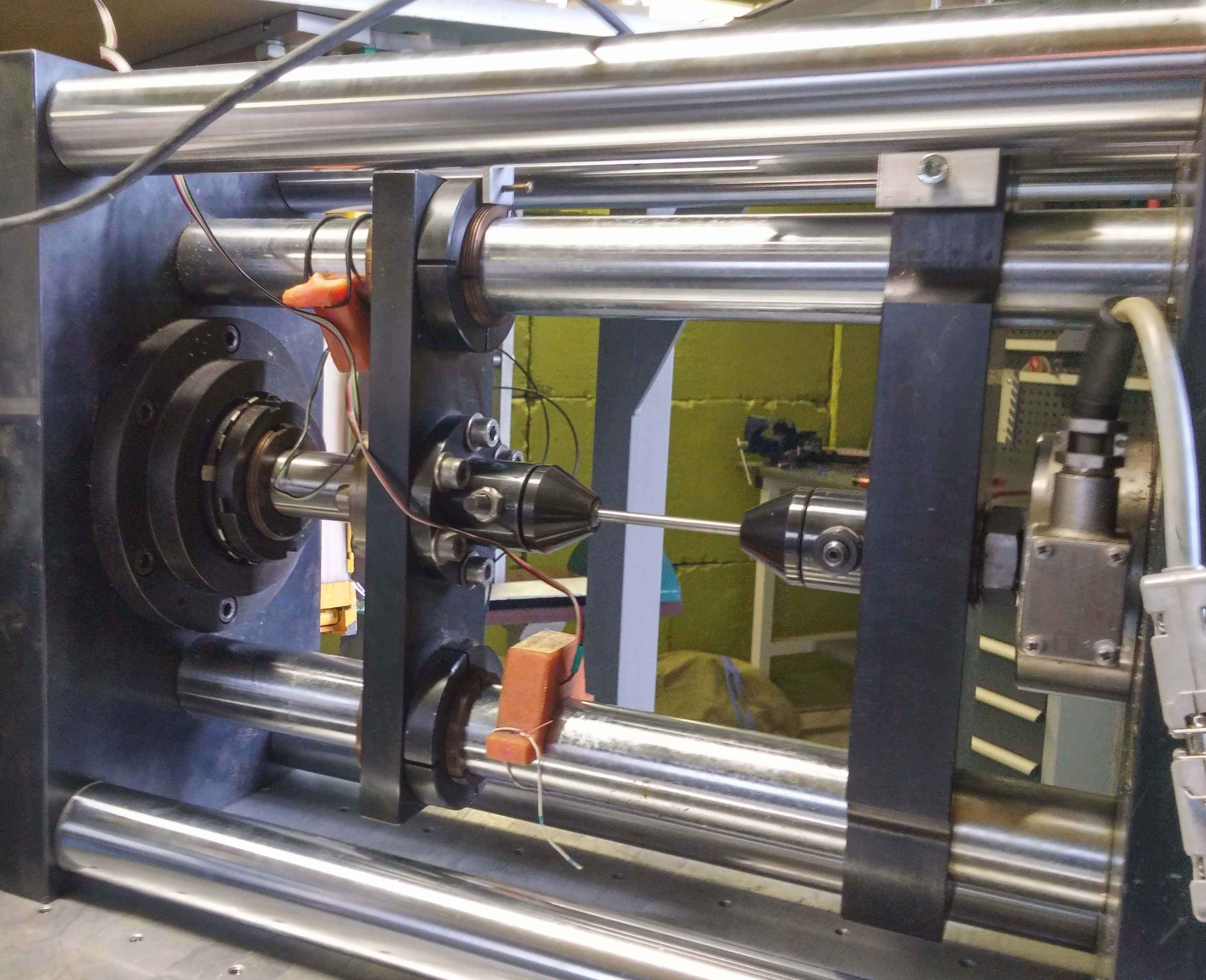
Fig.3b. Longitudinal and transverse strains of the crystal lattice of ferrite steel for different planes (hkl) depending on the load 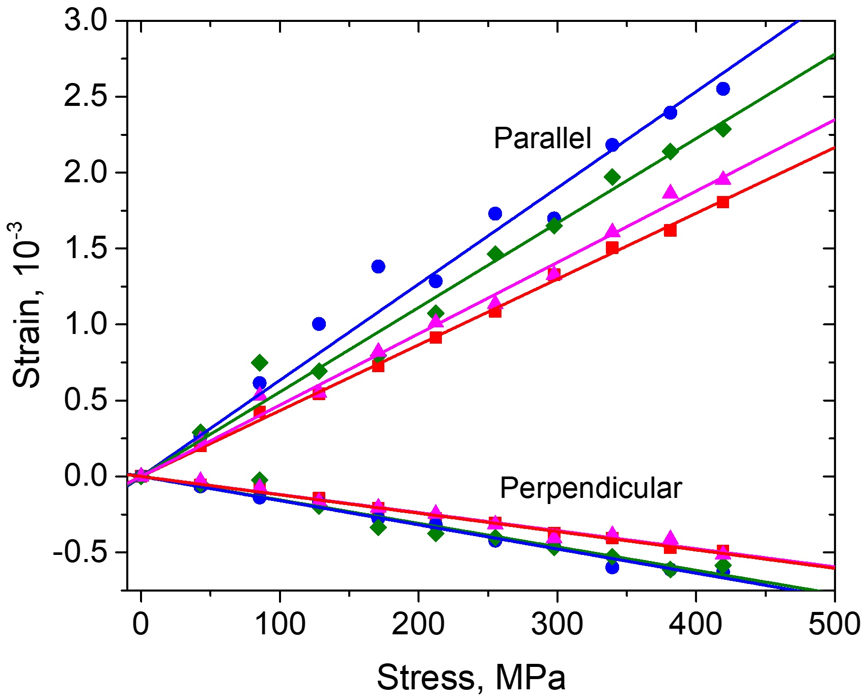
Fig.3c. The reciprocal lattice of the Young's modulus for different planes (hkl) depending on the orientation factor Гhkl 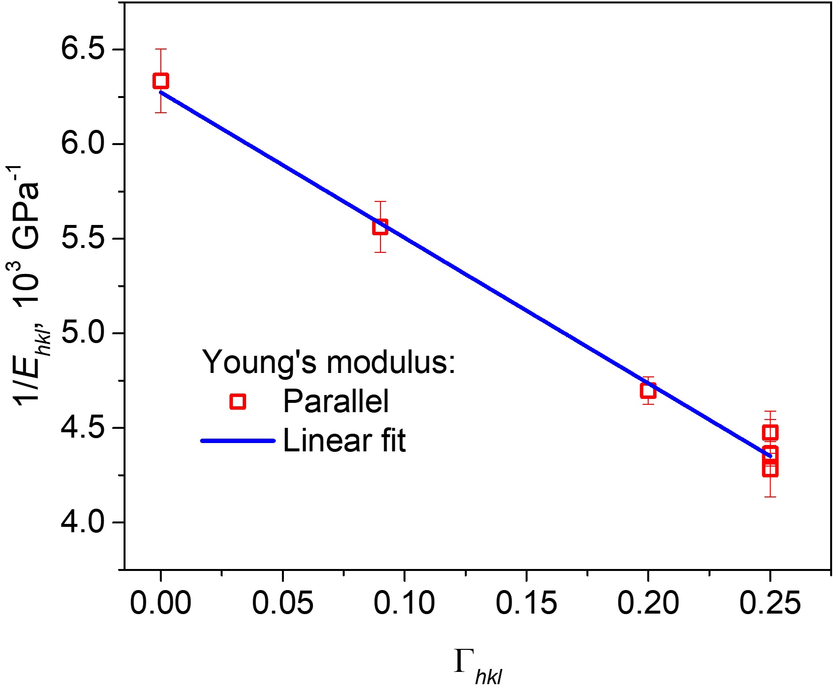
Publications:
- G. Bokuchava, Neutron RTOF Stress Diffractometer FSD at the IBR-2 Pulsed Reactor. Crystals, 8(8), 318 (2018). Doi:10.3390/cryst8080318
- G. Bokuchava, P. Petrov, G. Genchev et al., Residual stress analysis in welded joints by numerical simulation and high resolution neutron diffraction. Romanian Journal of Physics, 63, (7-8), 904 (2018).
- Г.Д. Бокучава, И.В. Папушкин, Нейтронная стресс-дифрактометрия по времени пролета. Поверхность. Рентгеновские, синхротронные и нейтронные исследования, 2, 5-11 (2018). https://elibrary.ru/yoteva